A key challenge in devloping a compressed-gas flotation aid is designing and iterating the buoyant structure.
My first attempts at this involved using a hotend and melting vinyl sheet together. However, I found that this method was extremely unreliable for creating perfect seams. Without a way to allow the hotend to smoothly glide over the plastic whilst melting it, I was forced to move onto another solution.
HH-66 Vinyl cement is specially formulated for reapiring vinyl inflatables. Whilst creating an effective seal, HH-66 is extremely hazardous. The in-built brush was difficult to use with accuracy, leading to drips of glue cementing undesired areas of sheet together.

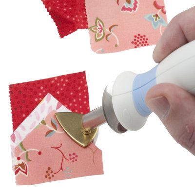
After speaking to my tutor Simon, I thought about his suggestion of buying an iron and using greaseproof paper as a protective lining between the hotend and the plastic. I found a ‘mini iron’ with variable temperature online. It is intended to be used for embroidery, and ended up being perfect for my own applications.
It took some roughly three times as long to design, cut and assembe these complex templates in card than to cut, trim & weld these shapes together in vinyl. It was a challenge creating a 3D shape that aesthetcially matched my sketches and provided sufficient volume, with perfectly matching seam lengths.
Insight: I should use surface-CAD in future models for two reasons:
- It enables quicker iteration cycles: by flattening 2D quilts taken from an already perfect 3D form in CAD. This is much quicker than having to messily edit panels as they are assembeld to realise a 3D form in card.
- It ensures perfect seam lengths, meaning that there are zero issues welding the complex curves together.
- It allows me to achieve any desired form with the minimal number of panels. This is key to assembly difficulty and reliability in-use.
- Flattening quilts allows me to print off templates instead of physically drawing them onto card. This increases modelling accuracy and reduces time taken.
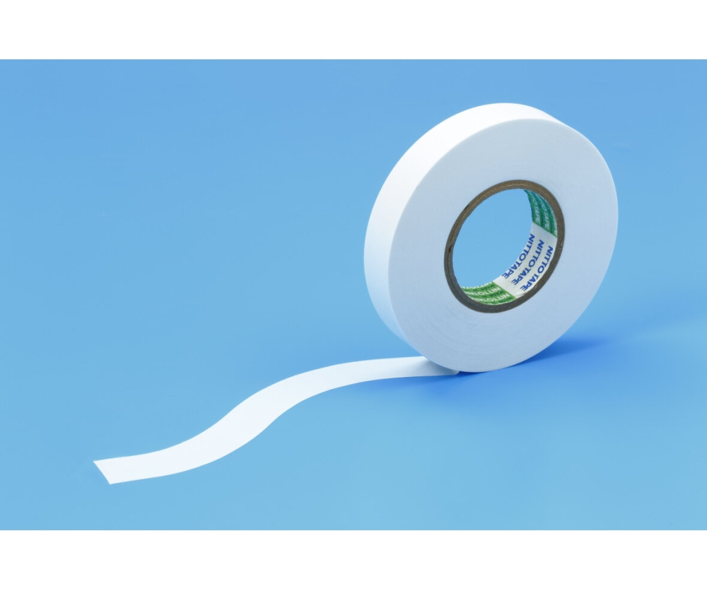
Following from Simon’s thought in greaseproof paper, I decided to use masking tape to line the welding surfaces. Whilst protecting the outer surfaces, this also made the edges on each panel perfectly flat. This made working and welding with the sheet much easier than If i had not lined these edges.
I expected to be able to remove the masking tape once welds had been made but it seems that the molten vinyl bonds to the tape, making it irremovable.
A key area of wasted time on this prototype was cutting and sticking so many pieces of tape to match the complex curves. I orginally decided to tape the outer edges of each panel, hoping that I could use this area to weld and form a seam at the marked line.
I found that whilst the assembly became more complex as more panels came in, it became increasingly difficult to hold secure these complex curves as I brought the hotend to them.
As the assembly reached a stage of near-completion, the inadequacies of my modelling technique in began to reveal themselves as small differences in seam length between panels. This could be partly down to the tape lining being less flexible than the vinyl sheet. Nevertheless, I hope to improve accuracy with future models.
Insight: I should find a more flexible tape!
- This would enable me to match the complex curves in the panels in single strips of pliable protection. Less time spent in this process, more favourable results.
Insight: I should devlop this structure in a way that involves a minimal number of seams.
- This will recuse assembly time and complexity. It will also improve overall reliability: fewer points of failure in the buoyant structure.
I had to abandon this prototype prior to completion. Its seams were beginning to misalign, making future panels difficult to install. I have,however, learned a ton from making this first prototype. Furure iterations should be much faster, with the use of CAD, printing and stretchy tape.
Skills gained:
- heat-welding vinyl
- assembling complex structures


